"AN INVESTMENT IN KNOWLEDGE ALWAYS PAYS THE BEST INTEREST" BENJAMIN FRANKLIN
"AN INVESTMENT IN KNOWLEDGE ALWAYS PAYS THE BEST INTEREST" BENJAMIN FRANKLIN

Research Article - (2022) Volume 59, Issue 1
Received: Mar 22, 2022, Manuscript No. BSSJAR-22-58014; Editor assigned: Mar 24, 2022, Pre QC No. BSSJAR-22-58014; Reviewed: Apr 05, 2022, QC No. BSSJAR-22-58014; Revised: Apr 07, 2022, Manuscript No. BSSJAR-22-58014; Published: Apr 14, 2022, DOI: 10.36962/GBSSJAR/59.1.003
Rotating machines are widely used in various industrial sectors. Their dynamic characteristics are normally given a lot of thought throughout the design process, especially when crack incidence is taken into account. The influence of a transverse crack in a rotor system on its dynamic behavior was explored in this study. To identify the dynamic parameters of a rotor in terms of vibration responses, natural frequencies, and critical speed, the job entails constructing a numerical model based on displacement-based finite element technique. In building the model, varied fracture depths at different positions along the rotor were taken into account. To test the validity of the developed approach, a numerical example of a rotor system was used. The numerical results demonstrate a distinct shift in the cracked rotating machine's vibration responses, natural frequencies, and critical speed. The size and form of the alteration were discovered to be a function of crack volume and location. The findings suggest a potential tool for an on-line diagnosis and monitoring system.
Cracked rotor, Rotating machine, Rotor dynamics, Critical speed.
Turbines, compressors, pumps, jet engines, and other rotating gear are subjected to varying stress conditions, making crack development inevitable. Their critical speeds and vibration responses in reaction to fracture onset are always key concerns. The undamaged natural frequencies of the rotor are represented by critical speeds. One of the key concerns that frequently lead to catastrophic failure in real-world operation situations is cracks forming in spinning machinery. Rotor failure occurs when the cross-section of the rotor that is not affected by the crack becomes insufficient to withstand the imposed load. When the crack reaches a critical size, it will fail quickly. Transverse cracks and longitudinal cracks are the two types of fractures that can be classified based on their geometries. Transverse cracks run parallel to the rotor shaft axis, whereas longitudinal cracks run perpendicular to the shaft axis. Transverse cracks are the most prevalent and dangerous because they weaken the spinning shaft by causing local flexibility in the rotor stiffness by concentrating strain energy in the crack zone. As a result, various studies have focused on such fissures.
The vibration-based technique was used in a large portion of the published literature on identifying and diagnosing rotor cracks. There are two types of signal-based and model-based approaches to this technology. Spectrum analyzers, proximity probes, and phase reference are used in signal-based methods to measure and monitor. Model-based strategies mimic cracked rotor behavior during operation using numerical or analytical models, and then connect the observed vibration pattern with the presence of a fracture at specific locations on the rotor.
The fundamental concerns include modeling cracked rotor dynamics and analyzing their dynamic response. In this case, a suitable mathematical model for the broken rotor is necessary for accurate dynamic response prediction. In this field of study, a great number of studies have been completed, and numerous notable achievements have been produced.
To the best of our knowledge, most studies primarily focus on evaluating alternative ways to analyze dynamic behavior of rotors with crack incidence, with limited research on analyzing the fractured rotor's instantaneous reaction during machine run-up. As a result, the focus of this study is on the dynamic behavior of a broken rotor during machine startup, taking into account varied crack depths and locations. The Timoshenko beam element was used, which had two nodes and four Degrees of Freedom (DOFs) per node.
Gyroscopic moments, translational and rotary inertia, and transverse shear deformations are all taken into account. To introduce the transverse fracture on the rotating shaft, an analogous beam element model is used. In addition, the model takes into account the rotary machine's geometry as well as the bearing supports' flexibility. To evaluate the dynamic behaviour of the broken rotor system, simulations for numerical examples are used. The impact of various fracture depths and placements on dynamic characteristics is thoroughly explored. The findings of this study may be useful for rotating machine designers, as well as for rotating machinery health monitoring and diagnosis [1-7].
Mathematical model for a cracked rotor
In order to undertake dynamic analysis in the design of modern machines, modeling and simulation techniques are widely used in the design stages and analysis of rotor-bearing systems. As a result, possible issues can be identified early in the design process. To address the issue of dynamic behavior of rotary machines in the presence of cracks, a finite element approach was used to construct a displacement-based computer model.
The rotor, which generates or transmits electricity from one location to another, is the most important component of any rotating machine. A spinning shaft carries various machine parts such as turbine wheels, impeller wheels, and gears in the rotor. In general, the rotor is not completely rigid, and in some situations, it is rather flexible. Two or more bearings can be used to support the rotor. Bearing location, stiffness, and damping qualities all play a part in determining dynamic performance.
The spinning shaft was modeled with a Timoshenko-type beam that took into account shear, rotational inertia, and the influence of gyroscopic coupling. Mass, polar, and diametric mass moments of inertia are added into typically stiff discs. Linear springs and dashpots can be used to model bearings. Finite element modeling approaches can be used to determine the rotor-bearing system matrix.
In this research, the transverse crack in a rotating shaft is modeled as a circular segment within the cracked beam element. Consequently, the crack influence can be expressed as the reduction in the element second moment of area at the crack position (Figure 1).

Figure 1: Modeling cracked beam section
Where hand w refers to depth and width of the crack respectively, θ is the angle proportional to crack depth and denotes the radius of the shaft.
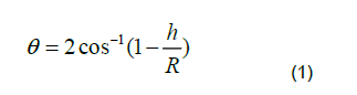
The angle (θ) can be found as in below:
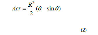
Consequently, for a given crack depth, the area of the cracked segment ( Acr ) can be determined by:
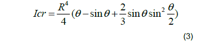
The moment of inertia of the cracked segment ( Icr ) can be defined as given below:
The effective moment of inertia of the cracked beam element ( Ie ) can then be calculated by:

Where:  denotes the moment of inertia of the uncracked beam element section.
Similarly, the effective cross-sectional area of the cracked beam element ( Ae ) can be determined from:
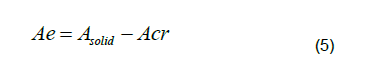
Here also, A solid describes the cross-sectional area of the uncracked beam element section.
Developing the rotor global matrices
The finite element procedure implemented in this work comprises of constructing the global mass, damping and stiffness matrices of the rotor-bearing system. The dynamic responses can then be identified by calculating the natural frequencies and mode shapes utilizing the global matrices of the rotating machine. The shaft is discretized into a number of Timoshenko beam finite elements. Each beam element has two-nodes with four lateral degrees of freedom at each node as shown in Figure 2.

Figure 2: Two nodes beam element with 4 DoF for each node
Where, u and v denotes translations in x and y directions while α and β represent right-handed rule of rotations about the horizontal and vertical axes respectively. The subscripts 1 and 2 refer to the first and second nodes respectively. The stiffness matrix Kele , mass matrix Mele and gyroscopic matrix Gele of the beam element are provided.
A spring element at a single node on the rotor was employed to approximate bearing stiffness. Bearing supports damping was used to add external damping to the rotor system. The assembly of the global system matrices (M, D, K) mass, damping, and stiffness matrices is made easier by computing the element's mass, stiffness, and gyroscopic matrices. Bearing contributions to stiffness and damping are accounted for in the global matrix. The collected global (M, D, K) matrices can be used to calculate the rotating machine's natural frequencies and mode shapes. The rotor system's partner matrix of state space can be described as follows:
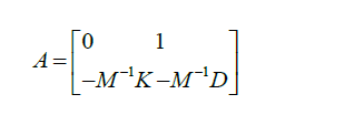
The imaginary part of the eigenvalues found from the above matrix produces the natural frequencies of the rotor system while the eigenvectors of it identifies the corresponding mode shapes. The general frame of the rotating machine finite element model developed in previous researches was utilized in developing the present numerical model to tackle with the issue of crack existing in the rotating machines.
Numerical example
The computational finite element model developed in this work was applied on a case study of rotor system for the sake of verifying the validity of the developed model. This rotating machinery comprises of a horizontal flexible shaft supported on two bearing supports with two rigid discs attached to rotor as shown in Figure 3.

Figure 3: A case study: rotating machine model
The rotor finite element model is demonstrated in Figure 4. The length of the rotating shaft is 1.0 m which was divided into 10 shaft elements. Consequently, 11 nodes with 4 DoFs at each node were generated. The details of the rotor model are defined in Figure 4 (Tables 1 and 2).
| Rotor shaft | Values |
|---|---|
| Elements number | 10 |
| Nodes number | 11 |
| DOFs number | 44 |
| Bearings number | Two bearings located at nodes number 1 and 44 |
| Shaft diameter | 20 mm |
| Stiffness of Bearing | 5.5 MN/m |
Table 1. Details of the rotor system model
| Rotor shaft | Values |
|---|---|
| Modulus of Elasticity (E) | 205 GPa |
| Poissons Ratio | 0.3 |
| Shear Modulus (G) |  |
| Density | 7800 kg/m3 |
Table 2. Shaft material properties

Figure 4: Finite element model of the rotor system
Three crack positions are considered in this work; Position 1: crack occurs close to left bearing. Position 2: crack appears away from left bearing and before disc 1. Position 3: crack exists between the two discs. In each position, various crack depths represented as a non-dimensional crack depth ratio are introduced. The crack depth ratio is defined as:
![]()
Where:$ is the crack depth ratio, refers to crack depth and denotes shaft diameter.
This study considers a wide range of crack depth ratios for each crack position. The generated model was utilised to determine the rotating machinery's vibration responses, Frequency Response Function (FRF), natural frequencies, and critical speeds. The results for a cracked rotor and an uncracked rotor shaft were compared to see how the existence of a crack affected the dynamic properties.
In this section, the findings of this study are reported. For various sizes and locations of cracks, the transient reaction (machine running up to 5000 rpm) and steady-state vibration responses are examined. At disc 1, the reaction is monitored in the Y-direction (vertical).
The greatest displacement responses for the three crack places are shown in Figure 5 over a wide range of crack depth ratios. The crack location 1 has demonstrated higher responses than the other two positions, as can be seen in this graph. Furthermore, as the net cross-sectional area approached the critical size, increasing the crack depth ratios reduced the displacement response. However, the crack position 1 curve indicates a tiny increase before rapidly decreasing (Figure 5).

Figure 5: Maximum displacement response for a wide range of crack depth ratios.
The findings of the displacement responses, frequency responses, and, as a result, the machine critical speed are obtained in each case of fracture positions, as detailed below.
The frequency and displacement responses obtained for fracture position 1 (10 mm distance from the left bearing support) are shown in Figures 6 and 7, respectively (Figures 6, 7A and 7B).

Figure 6: Frequency response during rotor running up for crack position 1

Figure 7A: Displacement response during rotor running up for crack position 1

Figure 7B: Displacement response during rotor running up for crack position 1
For crack position 2 (30 mm distance from the left bearing support), the results obtained for frequency and displacement responses are depicted respectively (Figures 8, 9A and 9B).

Figure 8: Frequency response during rotor running up for crack position 2

Figure 9A: Displacement response during rotor running up for crack position 2

Figure 9B: Displacement response during rotor running up for crack position 2
For crack position 3 (50 mm distance from the left bearing support), the results obtained for frequency and displacement responses are presented respectively (Figures 10, 11A-11C).

Figure 10: Frequency response during rotor running up for crack position 3

Figure 11A: Displacement response during rotor running up for crack position 3

Figure 11B: Displacement response during rotor running up for crack position 3

Figure 11C. Displacement response during rotor running up beyond critical speed for crack position 3
The critical speed of the cracked rotary machine was reduced in contrast to the uncracked case as a result of the reduced rotor stiffness due to the presence of a crack for the three crack positions investigated in this study, as can be seen from the results. Furthermore, the crack depth ratio, i.e. crack size, is found to be proportional to the drop in critical speed. In contrast, the results reveal that the response of the rotor during running up (frequency and displacement responses) increases as the crack depth ratio grows, particularly as the machine speeds up to its first critical speed (Figures 7B, 9B, 11B). However, the reaction with a crack depth ratio of 0.3 was shown to be larger than the uncracked example at critical speed, but a higher crack depth ratio (0.4) results in a lower response at critical speed. Furthermore, a noteworthy feature of crack position 3 was discovered, which is represented in a displacement response that is roughly 100 times larger than that of crack positions 1 and 2 as indicated in Figures 11B and 11C.
Figures 12 and 13 shows the influence of fracture position and depth on the critical speed and natural frequency of the cracked rotor, respectively. The critical speed and natural frequency decrease as the fracture depth grows, according to the results given in these figures. In addition, this reduction in critical speed and natural frequency is varying for the three crack positions. When a result, as the crack position approaches the supporting bearing, the fall in critical speed and natural frequency of the rotor increases (Figures 12 and 13).

Figure 12: Effect of crack depth and position on the critical speed

Figure 13: Effect of crack depth and position on the natural frequency
Finally, this reduction in critical speed and natural frequency is determined for a wide range of crack depth ratio for the three crack locations as detailed in Table 3.
| Crack Depth Ratio | Reduction in Critical Speed (%) | Reduction in Natural Frequency (%) | ||||
|---|---|---|---|---|---|---|
| Pos.1 | Pos.2 | Pos.3 | Pos.1 | Pos.2 | Pos.3 | |
| 0.1 | 0.7344 | 0.6169 | 0.3819 | 0.7035 | 0.5874 | 0.3574 |
| 0.2 | 1.5685 | 1.3302 | 0.7962 | 1.566 | 1.3148 | 0.8182 |
| 0.3 | 3.0968 | 2.6064 | 1.6647 | 3.0833 | 2.618 | 1.7032 |
| 0.4 | 7.8809 | 6.7979 | 4.5042 | 7.8315 | 6.8317 | 4.911 |
Table 3. Reduction in critical speed and natural frequency of the cracked rotor
The results show that as the fracture gets closer to the bearing support, the crack effect becomes more harmful due to the extra flexibility caused by the crack. A comparison with certain relevant literature is undertaken to validate the approach used in this study. In general, the findings of this study are consistent with those observed in these articles.
To examine the dynamic behavior of a spinning shaft with a transverse crack, the finite element displacement method was used in this study. The effect of crack position and depth on dynamic parameters (critical speed and natural frequency), as well as vibration responses, was explored during transient operation. To exemplify the effectiveness of the proposed method, a numerical case was presented. The findings demonstrate that the location and depth of the crack have a substantial impact on the rotor's dynamic properties. The natural frequency and critical speed of the rotor were found to decrease as the crack depth increased. Furthermore, as the crack approaches the bearing support, the loss in rotor dynamic characteristics becomes more pronounced. When compared to recent relevant literature, there is a lot of agreement. The findings provide a potential approach for a machine on-line monitoring system.